TFB24-SR-S | Damper Actuator | 22 in-lb | Spg Rtn | 24V | Modulating | Belimo
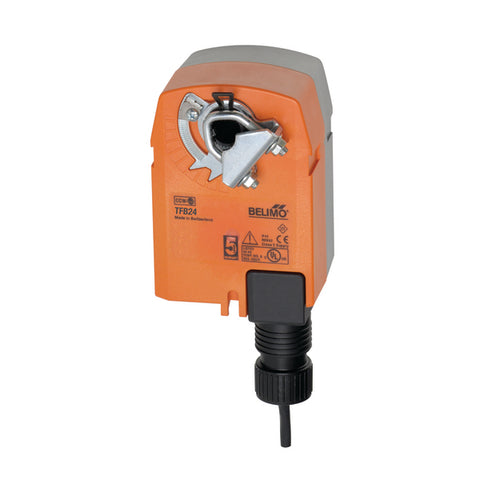
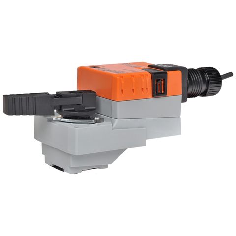
Damper Actuator, 22 in-lb [2.5 Nm], Spring return, AC/DC 24 V, 2...10 V, 1 x SPDT, modulating

Documents and manuals
Belimo TFB24-SR-S Documents
Overview
Details for TFB24-SR-S
Damper Actuator | 22 in-lb | Spg Rtn | 24V | Modulating
Damper Actuator | 22 in-lb | Spg Rtn | 24V | Modulating
Application
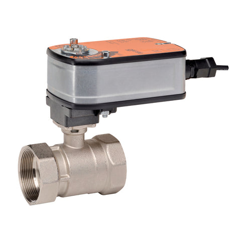
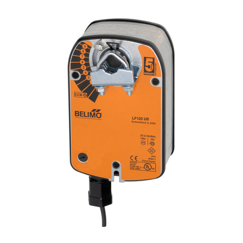
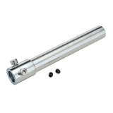
For fail-safe, modulating control of dampers in HVAC systems. Actuator sizing should be done in accordance with the damper manufacturer’s specifications. The actuator is mounted directly to a damper shaft from 1/4” up to 1/2” in diameter by means of its universal clamp, 1/2” shaft centered at delivery. A crank arm and several mounting brackets are available for applications where the actuator cannot be direct coupled to the damper shaft. The actuator operates in response to a 2 to 10 VDC, or with the addition of a 500Ω resistor, a 4 to 20 mA control input from an electronic controller or positioner. A 2 to 10 VDC feedback signal is provided for position indication.
Operation
The TF series actuators provide true spring return operation for reliable fail-safe application and positive close-off on air tight dampers. The spring return system provides consistent torque to the damper with, and without, power applied to the actuator. The TF series provides 95° of rotation and is provided with a graduated position indicator showing 0 to 95°. The TF uses a brushless DC motor which is controlled by an Application Specific Integrated Circuit (ASIC) and a microprocessor. The microprocessor provides the intelligence to the ASIC to provide a constant rotation rate and to know the actuator’s exact fail-safe position. The ASIC monitors and controls the brushless DC motor’s rotation and provides a digital rotation sensing function to prevent damage to the actuator in a stall condition. The actuator may be stalled anywhere in its normal rotation without the need of mechanical end switches. Power consumption is reduced in holding mode. The TF -S versions are provided with one built-in auxiliary switch. This SPDT switch is provided for safety interfacing or signaling, for example, for fan start-up. The switching function is adjustable between 0° and 95°.
Safety Note: Screw a conduit fitting into the actuator’s bushing. Jacket the actuator’s input and output wiring with suitable flexible conduit. Properly terminate the conduit in a suitable junction box.
Specifications
- Actuator Type
- Spring return
- Angle of Rotation
- 95
- Auxiliary Switches
- 1 x SPDT
- Control Type
- DC 2...10 V
- Degree of Protection
- IP42 NEMA 2 UL Enclosure Type 2
- Direction of Rotation (Fail-Safe)
- Reversible with cw/ccw mounting
- Electrical Connection
- cable
- Power Consumption (Holding)
- 1 W
- Power Consumption (Running)
- 2.5 W
- Running Time (Fail-safe)
- <25 s
- Running Time (Motor)
- 95 s /
- Safety Function
- YES
- Torque
- 22 in-lb [2.5 Nm]
- Voltage AC/DC
- AC/DC 24 V
Parts & Accessories


Reviews